The rapid development of technology has transformed traditional modeling methodologies and provided new ways to deliver digital 3D models and product data. Computer-aided design (CAD) now gives users the tools used in all stages of product development from concept development to final presentation. Not only are the products changing with technology advances, the tools we use to design the products are changing too.
So how exactly is augmented reality changing the way you do your work? Here are 3 ways Augmented Reality is reinventing your design process.
AR makes your workspace way more flexible
You won’t have to be constrained to your desk to design products anymore. AR allows you to take your design beyond where you traditionally have done the bulk of your work. With the help of smart glasses, tablets, and mobile phones, you can design, and experience your designs anywhere you want whether it’s at your desk, in a conference room, or on a shop floor.
AR allows you to fully conceptualize designs
Digitally generated 3D models created within CAD software have a limitation – the rendering of the design is still stuck inside of a flat screen. Augmented reality allows you to fully conceptualize designs when they’re superimposed on the physical world. Augmented reality allows you to sit inside your design as you’re creating it – enhancing engineers’ ability to evaluate and improve designs. This lets you fully appreciate characteristics of a design at full, partial, or expanded scale in its intended setting.
AR reduces time and money spent on prototyping
Augmented reality gives designers and engineers the ability to view accurate representations of finished products in real-world scenarios without expensive prototypes. It eliminates the constant need to build multiple and costly prototypes because you’re able to see any design flaws in a half virtual, half physical world. By the time you’re ready to send your draft to a 3D printer or manufacturer, you’re already very confident in your design.
If you’re not already using AR in your design process, it probably won’t be long before you are. Companies like PTC are leading the way to innovation and new design processes by integrating Augmented Reality (AR) capabilities into their CAD software, Creo Parametric. Creo AR allows you to rapidly create AR experiences directly from Creo, easily manage and control viewer access, rapidly distribute and share AR experiences, and effectively communicate and collaborate design information.
Start creating, publishing, and sharing augmented reality experiences with Creo AR – download the datasheet to learn more.
On March 19th, 2018, PTC released the newest version of Creo Parametric – Creo 5.0. It brought with it new functionality and tools to improve design and help engineers and designers bring the physical and digital worlds together with augmented reality (AR) and smart, connected design.
“Product design is fundamentally changing, and Creo continues to evolve to meet the needs of our customers. With Creo, companies can go from the earliest phases of design to a smart, connected product,” said Brian Thompson, Senior Vice President, CAD Segment, PTC. “Improved functionality and new capabilities, like additive manufacturing, set Creo apart, and give companies a true competitive edge all the way from concept to manufacturing.”
The release includes advanced AR capabilities that ease the beginning stages of your product design process. Watch the EAC’s tip of the week on creating AR experiences from Creo here. The newest additions also provide designers and engineers with the tools to increase productivity, improve optimization, and get products to the market faster. So what’s new in Creo 5.0?
Subscription-Only Pricing & Annual Releases
Creo 5.0 and all future releases will only be available as a subscription. Unlike previous releases, there is no perpetual-license pricing available for new Creo Parametric seats. Ask an EAC representative about the current Reactivate Program to move to new Creo versions and packages at up to 23% off the list price of a new subscription license.
In October of 2017, Paul Sagar, VP of Product Management, Creo, announced the new annual release schedule for Creo software. The announcement showcased that going forward, PTC will release their CAD software each year to keep their customers up-to-date with the newest technology.
Creo 5.0 New Capabilities & Extensions
Topology Optimization Extension
Often times it’s a challenge to get past barriers to innovation with new physical designs due to already existing designs and practices. The new Creo Topology Optimization Extension automatically creates optimized parametric geometry based on a defined set of objectives and constraints. It’s a huge time-saver. The extension accelerates innovation without the limitations of existing designs and thought processes. It helps create improved designs without the over-engineering, additional weight, and additional material found in some designs.

Additive and Subtractive Manufacturing for metal 3D printing
Creo 4.0 enabled users to design optimize, and additively manufacture parts without the need to use multiple softwares – but now the Creo Additive Manufacturing Plus Extension for Materialise in Creo 5.0 extends support for metal 3D printing. New tools in the extension help generate and optimize custom support structures and weight/material saving lattices.
Mold Machining Extension
The new Creo Mold Machining Extension provides dedicated high-speed machining capabilities optimized for the creation of molds, tools, dies, electrodes, and prototype machining. These new capabilities can be used in complex machine designs to generate optimized design paths.
Creo Flow Analysis Extension
The Creo Flow Analysis Extension is a computational fluid dynamics (CFD) solution allows users to integrate analysis early and often to understand product functions and performance. The extension allows designers and engineers easily and quickly simulate fluid flow directly within Creo.
Productivity Improvements
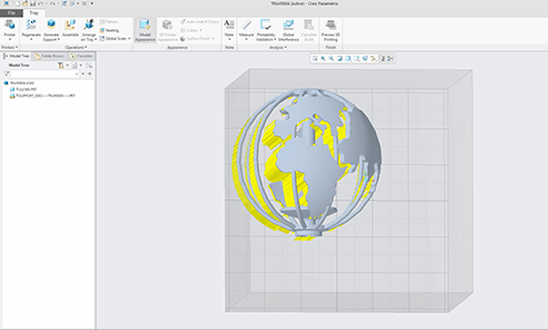
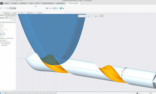
Creo 5.0 includes many productivity enhancements such as an improved user interface, geometry creation with sketch regions, subdivisional modeling, surfacing, sheet metal tools, and volume helical sweeps.
Creo 5.0 also offers the Creo Collaboration Extension for Autodesk Inventor to help organizations consolidate onto a single CAD system and work with even more vendors/suppliers.
This reduces cost and effort associated with maintaining multiple systems and enables better collaboration throughout an enterprise.
Bring your design process to the next level with Creo 5.0.
PTC’s Service Information Manager adds three advanced capabilities to the XML authoring and content management system:
- Translation Management
- Part List Generation
- Publication Structures
My last blog focused on Publication Structures. You can read more about publication structures here: Revolutionizing Book Assembly with SIM. Next time I will discuss Translation Management. However, today I’m discussing Part List Generation, how to create value from part data.
The Engineering Bill of Material (BoM) is structured based on the design. The Service BoM is then derived from the Engineering BoM. With the part structure defined, you can visually identify parts and add them to various service kits and assemblies and ultimately generate a part list from the structure that can be used in technical publications. Updates from source parts and drawings to downstream processes are practically automatic. Building part lists with associative, up-to-date service information increases the accuracy of information and improves authoring efficiency thereby reducing time to market.

Each component in a drawing can be a part with its own lifecycle that is managed and repurposed in an integrated system. All too often we see disparate systems with Engineering drawings in one system and part data management in another.

Many users of Windchill use it as a CAD warehouse to store content more or less. Sure users of the design engineering tools find them extremely valuable, many folks are leveraging workflow processes and lifecycle features to expedite the day-to-day flow of information, and many have found that the change management tools add value when it comes to maintaining change integrity and traceability. Nonetheless, many organizations are not leveraging their parametric data for parts management (you know who you are).
The ability to repurpose Engineering design part structures to create Part Lists for Service information is the promise land. But the system can only repurpose parts if they exist as parts in the system. Generating part lists for catalogs and online delivery requires parts with end items and part structures. So in other words, using Windchill Service Parts and Service Information Manager requires part data management in Windchill PDMLink.
Service parts management provides an out-of-the-box method of generating Part Lists for the technical documentation community from a single source of information. As a result, organizations are able to greatly improve the process of information delivery and are able to leverage dynamic publishing capabilities to bring products to market faster, and keep customers better informed.
Learn More
Refer to PTC’s web site for a complete description of Service Information Manager.
EAC information solution experts have decades of reliable XML solution experience. Explore the EAC website to learn more about our products and services or review the Product Development Information Services Brochure.

Many PTC Creo users may be surprised to discover that hidden in their Creo file directory, there are two powerful CAD automation tools just waiting to be utilized! Creo Web.Link and Creo J-Link are two API tools that are packaged with all Creo installs; no extra licensing necessary. Both tools provide a way to access and modify your CAD data from a custom User Interface (UI) or a webpage.
The question is, what benefits can you reap from these tools? Perhaps there are technical staff members that don’t know the Creo tool, but they want to generate drawing PDF’s by entering some dimensional and parameter information. Conceivably, customer orders could be retrieved from a database to drive CAD or generate a Point of Departure (PoD). There are many opportunities that may arise where a UI is more efficient than modifying your CAD data directly in Creo. Today, we’ll focus on Web.Link due to its relative simplicity compared to J-Link.
Web.Link utilizes Creo’s embedded browser to reach into your CAD session and touch almost every aspect of a model, assembly, or drawing. A user builds a webpage and connects to the CAD using the JavaScript API. One caveat of Web.Link is that a user MUST use the embedded browser, whereas with J-Link, the program you create can run asynchronously – meaning Creo does not have to be running to use it.
The full functionality of Web.Link is documented in your Creo install directory at ‘[datecode]Common Filesweblinkweblinkug.pdf.’ There is also a searchable API located in the same directory which provides more detailed information on all the available features. The documentation may be a bit overwhelming at first, but here are the basic steps.
Basic Steps of Getting Started with Creo Web.Link
- Create a web page with text input, buttons, and anything else that you may use to access or modify your CAD. For example, you may have some dimensions or parameters you may want to modify. You may want to run a macro (mapkey). Or, you may just want to display relevant model information.

Figure 1: Basic HTML page - Use the JavaScript objects, classes, methods, etc. to connect everything to CAD.
Figure 2: JavaScript function that accesses CAD data and populates the webpage text boxes - Open the webpage in your Creo embedded browser and try it out! There are prepackaged examples for you to try in the Web.Link directory if you don’t want to jump in the deep end right away. There is also a ‘pfcUtils.js’ file that comes in handy for many of the Web.Link programs you’ll write. It’s a library of useful pre-built functions that many of the examples use.
Figure 3: Retrieving model and session information from Creo through the embedded browser


A couple of Items to Note:
- Be sure to read the section in the Web.Link User Guide that addresses browser security. Running javascript in an Internet Explorer (IE) browser session typically sets off red flags and you’ll have to configure your IE security to enable the ActiveX scripts. Alternatively, you can use the Mozilla browser, and use a few lines of code in your JavaScript (See Figure 2) to address it.
- There are a few configuration options that must be enabled to allow Creo Web.Link to access the CAD session. The relevant configuration options are:
- WEB_ENABLE_JAVASCRIPT
- WEB_LINK_FILE_READ
- WEB_LINK_FILE_WRITE
- WEB_LINK_PROE_READ
- WEB_LINK_PROE_WRITE
Creo Web.Link is a simple tool that can make a huge difference in how your company interacts with its CAD data. I encourage you to skim through the Web.Link User Guide and try out some of the examples provided. If you have any questions about Web.Link, please direct them to the comment section. If you have any questions related to CAD Automation services provided by EAC, please contact us! If you need an extra copy of the PTC Creo Web.Link User Guide, click the image below to download.

If you are an OEM supplier to a major fortune 500 manufacturing company it probably took you a while to become their supplier. You had to prove to them that you could deliver a quality product on time, at a fair price.
Now that you have won their business it is probably equally as important to maintain that business as it was to win it in the first place. Your company probably has a nice cash flow and your employees are enjoying a nice secure job because of this win. However, the most important thing that will keep your customer coming back to you is quality.
Most major manufacturing companies realized years ago that the sooner that you can discover flaws or issues in the design phase, the easier and more cost-effective it is to fix the problem.
They found out that after completing the design process in CAD, they could move on to using simulation software, like ANSYS, to simulate prototypes. By simulating their prototypes they are able to run multiple simulations of their prototypes at one time and pick out the prototype that met their requirements to move forward and begin manufacturing.
Over the years these huge corporations have saved millions of dollars in time-savings and reduced the amount of times projects have to be constructed.
In the interest of time-savings and cost-savings, I suggest you consider looking into a simulation tool yourself. As your customer will appreciate knowing that their supplier realizes how important a quality product is. Who would you rather buy from? A company that has thoroughly tested their product or one that hadn’t?
If you’re interested in learning more about the benefits of simulating your products early and often, learn more about simulation here.
The increased use of 3D printing, from hobbyists to professionals, has revolutionized the way ideas and products are brought to life. Multiple websites (GrabCAD, Thingiverse, etc.) provide over a million free downloadable files that can be printed on a variety of 3D printers. Everything from miniature drone blades to sci-fi figures to replacement parts for your vacuum cleaner are readily available. The possibilities for whatever application you have are almost unlimited. Almost.
The key to giving your 3D designs unlimited potential for customization is CAD modeling software. While there are many accessible 3D printing files created by others, the most satisfying way to bring your ideas to reality are files created by you! Files for 3D printing can be created from scratch or existing files can by modified to suit your application. Without the ability to create unique parts, a 3D printer can quickly become a novelty. As soon as the excitement of first initial prints wear off, the use and return on investment reduces as well.
Read more to see how one company unlocks the true potential of CAD with 3D Printing.
Engineering Services Customer Case Study
A company that customizes enclosure trailers recently proved to be an excellent example of this limitation and how to solve it. The company wanted to use an off-the-shelf LED lighting product to illuminate the interior of a racing trailer. They needed to mount the LED lights in a clean manner and in specific locations to satisfy the customer’s needs. The company also wanted to locate the lighting switches discreetly. Since these parts would not be mass-produced the cost of a plastic injection mold could not be justified. They decided a series of 3D printed components would be the best method to meet their needs within the given delivery timeline.

While the company had access to a 3D printer, they did not have access to CAD modeling software. Despite extensively searching online trying to fulfill the requirements for these lighting components, nothing could be found to suit their needs.
The company came across EAC and decided to utilize the Engineering Services Group to save the day. A member of the Engineering Services Team created several CAD models using PTC Creo to design the customized lighting components. Within two hours, the stylized CAD models were complete and ready for printing. Three days later the 3D prints were finished and installed in the trailer.

Figures 1 illustrates the CAD with 3D printing files and Figure 2 illustrates the finished parts installed in the  trailer. The parts were 3D printed using the Form 2 by FormLabs. The Form 2 is a high-quality stereolithography (SLA) 3D printer. In this case, the parts were printed using a clear resin (GPCL02) and then painted black. The parts were quickly produced to provide the custom enclosed trailer with a lighting solution that exceeded the customers expectations.

This project demonstrates a practical application of 3D printing when paired with CAD modeling software. With PTC Creo and the Form 2, the Engineering Services team was able to quickly create finished and functional parts that can provide unique and differentiating products without the capital investment sometimes required by plastic injection molding and other manufacturing processes.
It’s important to remember that the quality of your print depends on the quality of your design. If the CAD model is poorly designed, your 3D printed product may have flaws. The cleaner your design, the cleaner your print. Luckily for you, we can help! Find out why you should design your products using PTC Creo here. If you think you already have a great CAD modeling software and want to explore the Form 2 instead, go here.