This is a guest post from our friends over on the Formlabs Blog.
What do Formula 1 race cars and Marine One have in common? Many of their high-performance drivetrain and engine components started life in Kapfenberg, a quiet little town nestled in the Austrian Alps.
Pankl Racing Systems specializes in developing and manufacturing engine and drivetrain components for racing cars, high-performance vehicles, and aerospace applications with more than 1,500 employees, and worldwide subsidiaries in Austria, Germany, the United Kingdom, the United States, Slovakia, and Japan.
Every single part that Pankl makes requires a series of custom jigs, fixtures and other tooling that are designed and fabricated specifically for that part. The result is a proliferation of custom tools, adding significant cost and complexity to the manufacturing process.
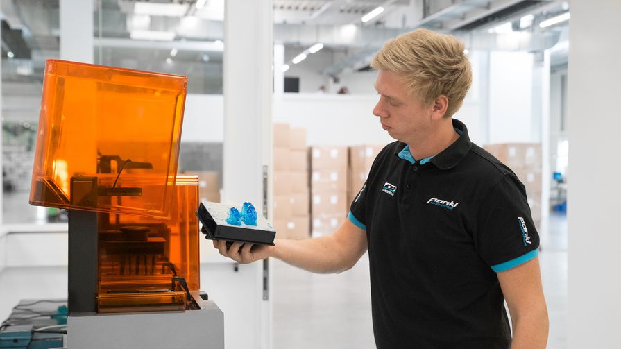
To fulfill tight production deadlines, process engineer Christian Joebstl and his team introduced stereolithography (SLA) 3D printing to produce custom jigs and other low-volume parts directly for their manufacturing line in the company’s new €36 million state-of-the-art manufacturing facility.
While 3D printing was initially met with skepticism, it turned out to be an ideal substitute to machining a variety of these tools, surprising even Pankl’s demanding engineers. In one case, it reduced lead time for jigs by 90 percent–from two to three weeks to less than a day – and decreased costs by 80-90 percent, leading to $150,000 in savings. Read on to learn how Joebstl and his team implemented their new 3D printing-based process.
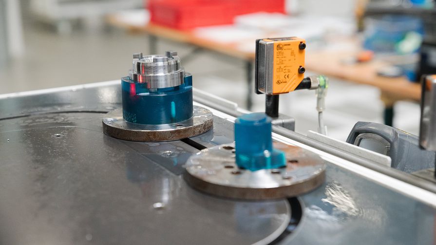
Custom jigs in-use for motorcycle gear manufacturing
Pankl has been in the business for more than 30 years. Has 3D printing been a long-standing part of your practice?
Surprisingly, not at all. We didn’t have any 3D printers until less than a year ago. A colleague of mine had a request for a custom cover to hide some areas from impact in a shot peening machine. We used to buy parts like this from an external supplier, and one such tooling cost about €1,200. I was thinking ‘there has to be another way.’
Having been familiar with 3D printing from my education, I started looking and found the Form 2 3D printer after reading some reviews online. My colleagues understand the value in 3D printing now, but at the beginning, they were extremely skeptical. They thought 3D printing was more like a toy.
In our business, we expect that good equipment is inevitably also expensive. Most of our machinery starts at $100,000 and goes well beyond that. When my colleagues saw that the Form 2 only costs about $3,500, they asked me, “Why should we buy a toy?”
We ordered multiple custom sample parts to conduct tests, and it turned out that the 3D printed parts were capable. Holes and length tolerances were within the ±0.1 mm interval. I researched the material costs for my amortization calculation and discovered that a 3D printed set of the tooling for shot peening would only cost $45. I summarized this into a presentation for the board and took the parts to the kickoff meeting of the new gear plant. They were finally convinced, and we decided to buy our first Form 2, which we soon scaled up to three units.

In what cases has 3D printing helped trim production timelines and save costs?
Pankl was selected to manufacture entire gearbox assemblies for a well-known motorcycle manufacturer in 2016, and we swiftly began to set up the new production facility. Manufacturing these gears is an elaborate process. Forged steel parts go through multiple stages of machining using automatic lathes, followed by heat treatment and stress relief.
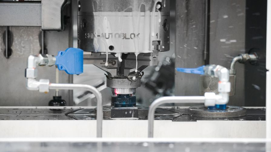
Each stage of turning in the automatic lathes requires custom jigs for every individual gear type. Machining these parts is costly, and adds significant complexity and risk to the manufacturing process.
Our schedule was tight because we had to produce many more gear types than expected. By the time we got to designing and ordering tooling, we were already supposed to start producing the first acceptance lots. We couldn’t just design the custom jigs and get them next day. If we had outsourced to traditional machining service providers, we would have had to wait six more weeks before we could start production–so we decided to produce the parts in-house on our Form 2 3D printers.

With 3D printing, you can simply take the same design, send it to the printer, and then have the finished part ready by the next morning. This leaves time to check the part on the manufacturing line and make any necessary changes. It also simplified the design process, providing the design freedom to produce jigs in any shape. In conventional CNC milling or turning, you are constrained by the need to design machinable parts, and every extra curve, hole, or chamfer adds complexity to the process.

Using a single Form 2, we can print a single jig in 5—9.5 hours, and running all three of our machines enables us to produce about 40 jigs within a week.
A simple machined jig costs about $40—50, but more complex parts can cost up to $300. 3D printing reduces these direct costs to $8.5—25, and significantly lowers overhead costs in design, purchasing, and storage, resulting in more than 90 percent overall cost reduction. Considering we’ll have to produce more than 1,000 jigs over the course of production, 3D printing will help the company save more than $150,000.
How did these parts fare on the production line?
We’ve had lots of problems in the past because the cooling media in the lathe is very aggressive on plastic parts, and makes them brittle after some time. Parts 3D printed with Tough Resin have shown resistance against our cooling media, and they are strong enough to withstand the intermittent load that these parts have to endure. Holes and length tolerances normally lie within the ±0.1 mm interval, which satisfies the requirements for our jigs.

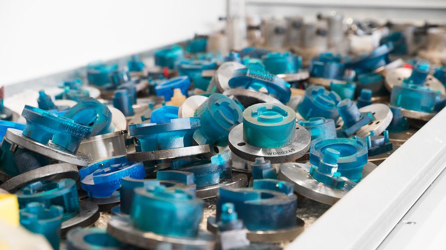
We’ve already produced more than 300 3D printed jigs to manufacture small batches of 200 parts of each gear for the trial production run. Soon, we’ll scale up production to 1,000-2,000 parts per batch and the production capacity of the facility will increase to more than 1.5 million gears per year.
What are some other applications where you have used 3D printing?
Prototyping, shot peening, masking, and manufacturing various jigs and tooling. For example, when we have a new connecting rod design, we 3D print prototypes to discuss complex features on the part. It’s much easier if you can look at the part, and hold it in your hands.
Once we had to design a custom connecting rod for a customer, who wanted to verify if it’d fit into the building room of a cylinder and that it wouldn’t hit the chamber or the cylinder head itself while turning. We 3D printed a prototype and sent it to them. Once they confirmed that the design worked, we could start production with confidence. The alternative would have been to produce a machined part, which would have been more expensive for the customer and required eight weeks of waiting time.
We also 3D printed special adapters for grippers on an automated handling system. To achieve the perfect grip between the gripper and the part, you have to take the negative of the part, and form the fingers of the gripper according to the shape of your part. Normally we would have milled or cast it, which would have been substantially more expensive.
Recently, we used Flexible Resin in a shot peening machine to increase the friction between the self-cleaning jigs and some other parts. The friction between the metal parts was too low to transfer the turning movement. I added some 3D printed elastic brakes in the tooling to increase the friction so that the turning movement was transmitted from the bottom to the top. Getting these parts from an external vendor would have taken weeks.
Do you have any other plans to use 3D printing within Pankl?
One of my goals is to get more orders from other divisions within Pankl. We’ve had success with 3D printed parts in our production line, and I see countless other applications that could benefit from 3D printing. I want to show other engineers the parts we make, and the applications where we use them, to make them aware that this technology is available to them in-house.
I started with this project when other colleagues showed interest in our new processes. I sent around information on the 3D printing materials, such as their mechanical properties, what they look like, and the particular use cases they’re suitable for. I also printed sample parts for other departments, described the design specifications and how they can order something.
SEE WHAT YOU CAN CREATE WITH A FORM 2
Explore the materials to discover the one that fits your needs.
Request a Free Sample
We’ve already printed parts for aerospace and drivetrain divisions. They send us the designs, we produce the parts for them, and they receive finished parts that are ready to use in their machines. Pankl is a large company, though, which makes this a slow process. We have to overcome the same hurdles as we did initially within our department, and I believe many other companies have these concerns about 3D printing.. But looking at the results we’ve achieved, I’m positive that they’ll recognize the value in the technology.
The increased use of 3D printing, from hobbyists to professionals, has revolutionized the way ideas and products are brought to life. Multiple websites (GrabCAD, Thingiverse, etc.) provide over a million free downloadable files that can be printed on a variety of 3D printers. Everything from miniature drone blades to sci-fi figures to replacement parts for your vacuum cleaner are readily available. The possibilities for whatever application you have are almost unlimited. Almost.
The key to giving your 3D designs unlimited potential for customization is CAD modeling software. While there are many accessible 3D printing files created by others, the most satisfying way to bring your ideas to reality are files created by you! Files for 3D printing can be created from scratch or existing files can by modified to suit your application. Without the ability to create unique parts, a 3D printer can quickly become a novelty. As soon as the excitement of first initial prints wear off, the use and return on investment reduces as well.
Read more to see how one company unlocks the true potential of CAD with 3D Printing.
Engineering Services Customer Case Study
A company that customizes enclosure trailers recently proved to be an excellent example of this limitation and how to solve it. The company wanted to use an off-the-shelf LED lighting product to illuminate the interior of a racing trailer. They needed to mount the LED lights in a clean manner and in specific locations to satisfy the customer’s needs. The company also wanted to locate the lighting switches discreetly. Since these parts would not be mass-produced the cost of a plastic injection mold could not be justified. They decided a series of 3D printed components would be the best method to meet their needs within the given delivery timeline.

While the company had access to a 3D printer, they did not have access to CAD modeling software. Despite extensively searching online trying to fulfill the requirements for these lighting components, nothing could be found to suit their needs.
The company came across EAC and decided to utilize the Engineering Services Group to save the day. A member of the Engineering Services Team created several CAD models using PTC Creo to design the customized lighting components. Within two hours, the stylized CAD models were complete and ready for printing. Three days later the 3D prints were finished and installed in the trailer.

Figures 1 illustrates the CAD with 3D printing files and Figure 2 illustrates the finished parts installed in the ![]() trailer. The parts were 3D printed using the Form 2 by FormLabs. The Form 2 is a high-quality stereolithography (SLA) 3D printer. In this case, the parts were printed using a clear resin (GPCL02) and then painted black. The parts were quickly produced to provide the custom enclosed trailer with a lighting solution that exceeded the customers expectations.
trailer. The parts were 3D printed using the Form 2 by FormLabs. The Form 2 is a high-quality stereolithography (SLA) 3D printer. In this case, the parts were printed using a clear resin (GPCL02) and then painted black. The parts were quickly produced to provide the custom enclosed trailer with a lighting solution that exceeded the customers expectations.

This project demonstrates a practical application of 3D printing when paired with CAD modeling software. With PTC Creo and the Form 2, the Engineering Services team was able to quickly create finished and functional parts that can provide unique and differentiating products without the capital investment sometimes required by plastic injection molding and other manufacturing processes.
It’s important to remember that the quality of your print depends on the quality of your design. If the CAD model is poorly designed, your 3D printed product may have flaws. The cleaner your design, the cleaner your print. Luckily for you, we can help! Find out why you should design your products using PTC Creo here. If you think you already have a great CAD modeling software and want to explore the Form 2 instead, go here.