PTC’s Technical Specialist for Mathcad, Anji Seberino, joined us on today’s webinar called “Plotting Your Success with Mathcad Prime 5.0” to demonstrate how 2D plots have evolved in PTC Mathcad. This information technology and leading engineering calculations software is the number one tool for designers and engineers in the industry. Download the PTC Mathcad Prime 5.0 brochure.
Let’s talk about plots. PTC listened to their customers and responded to suggestions and requests needed for Mathcad Prime. The old plotting method is still available for those that need to use it, although the new improvements gave plots the abilities to add a title, a legend, gridlines, axis labels, a 2nd y-axis, and richer formatting options.
Anji demonstrates how you can calculate stress using input variables of force and area on your Mathcad worksheet:

The original way to create a plot in PTC Mathcad Prime 4.0 was to go to the ‘plots’ tab and click ‘insert plot’ – this function is still here.
With the old way (which you can still use), you would follow these instructions:
-insert plot
-x-axis= force
-y-axis= σ2
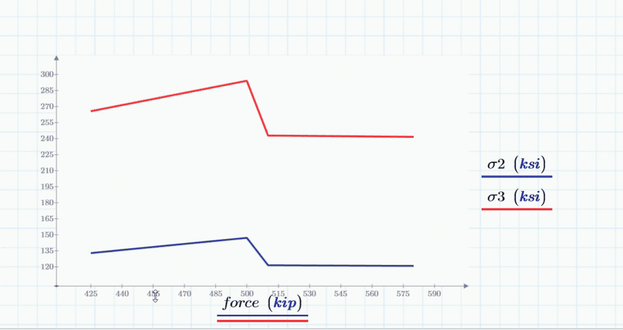
You can see that ‘force’ and ‘σ2’ are names of variables that store our mathematical data – but they are NOT labels. You cannot add the labels using this old method (but you can with the new).
The new way is NOT on the plots tab – it’s on the math tab – called the ‘chart component’.
-go to ‘math’ tab
-click on ‘chart component’
-right click on the chart, click on ‘insert x-axis expression’
-right click on the chart, click on ‘insert y-axis expression’
On previous version of Mathcad you could not enter a 2nd y-axis. Now you can:
-right click on the chart, click on ‘insert y-axis expression’
In the chart component you can access all the rich format options in one place with a lot more room to make the plot the way you want it to look with styles, the legend, a title and where you’d like the location of all of these components to be while being able to change background, text, and line colors, borders, and opacity settings.
PTC Mathcad helps you calculate and solve engineering problems. Much more can be done in charting your 2D plots in Mathcad Prime 5.0 – watch the webinar replay here.
EAC’s been in the engineering and design technology world for a long time. Over the years we’ve carefully cultivated our product portfolio to meet the ever-changing needs of people and companies that design, manufacture, and service products. Our partnerships with PTC and ANSYS allow us to offer a few different design simulation and analysis solutions to our customers.
Design simulation, Computer Aided Engineering (CAE), Finite Element Analysis (FEA), Computational Fluid Dynamics (CFD), and many other terms all fall into the “simulation and analysis” bucket. These tools help engineers and designers create virtual prototypes of their products. This helps groups rapidly prove, or disprove, design ideas in a digital space – reducing the time and money spent on physical prototypes, and increasing confidence in designs.
“If you’ve seen one, you’ve seen ‘em all” does not apply to simulation software. Different tools offer different benefits, accuracy, speed, and ease-of-use. Here’s a quick overview of some of the tools we offer. Contact our sales group to learn more about pricing, full capabilities, and packaging.
Option 1) PTC Creo Simulate
Simulate is a fantastic tool that’s fully integrated into PTC Creo Parametric CAD software. It offers fantastic meshing capabilities and accurate simulation results directly within a user’s familiar CAD software interface. All you need to do select the PTC Creo Simulate tab and you’re off and running. This is great for designers and engineers looking to test the stresses and loads under which a product will operate in ‘real world’ conditions. Based on your simulation and analysis results, you can either fix design flaws or forestall them. If you’re already using PTC Creo you should explore PTC Creo Simulate. Because, why would you ever manufacture a product without testing and analyzing it first? Creo Simulate comes in two flavors – Simulate and Advanced Simulate. They come with two different price points. One or the other might be the best option for your company. It really comes down to whether you need to simulate materials with linear or non-linear properties.
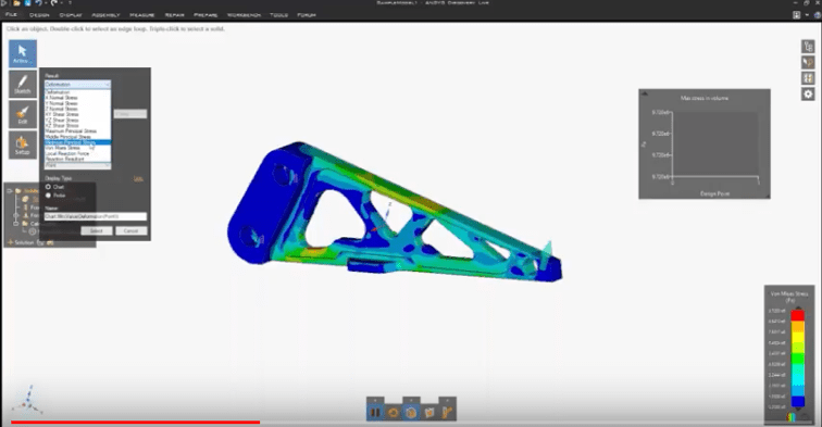
Option 2) ANSYS Discovery Live
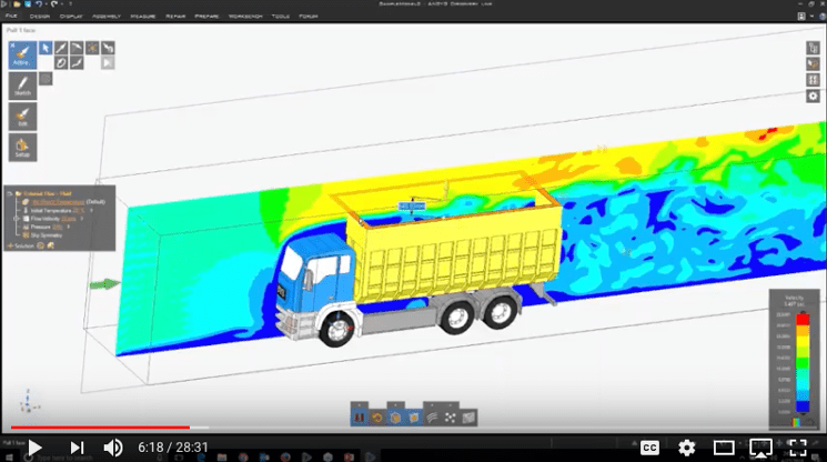
ANSYS Discovery Live blows my mind. This tool was released in late 2017 and delivers functionality never seen before. Discovery Live uses ANSYS Discovery SpaceClaim to pull in IGES, STEP, and CAD models. Then the interface guides users through applying materials and some constraints – and Boom! It runs the simulation…in real-time…right in front of you. I’m talking about the ability to run wind-tunnel testing in real-time! Discovery Live is different from PTC Creo Simulate and most other simulation tools. It uses the Graphics Card (GPU) to run the simulation. This means it doesn’t occupy your core processor and RAM to while solving. You get better computer performance and instantaneous results for structural, thermal, fluid flow, wind tunnel, structural/fluid interaction, and more. Discovery Live is a great tool for engineers and designers that want to test a lot of design options quickly. The price is incredibly reasonable for a tool this powerful. You can see pricing and compare Discovery Live to AIM here.
Option 3) ANSYS Discovery AIM
Sometimes simulating real-world conditions requires more features and control than tools like PTC Creo Simulate, Solidworks Simulation, or Discovery Live might offer. ANSYS Discovery AIM is a great option when that’s the case. ANSYS Discovery AIM is a “multi-physics” simulation tool. What does that mean? Multi-Physics or Multiphysics refers to the ability to combine properties and solvers to simulate product usage. “Physics” in the simulation world refers to the kinds of simulation you are running – e.g. electromagnetic, thermal, structural, radio frequency, fluid flow, etc. AIM is a workflow driven multi-physics tool. It guides users through the steps necessary to complete a successful simulation. This is the perfect option when companies want a robust solution, but may not have experienced analysts on staff. Much like how PTC Creo Simulate maintains a familiar interface to make simulations easier; AIM uses guided workflows to make detailed upfront simulation accessible to engineers and designers.
Option 4) Dedicated ANSYS analysis software
When product simulation and analysis goes to the next level you need the ANSYS flagship products. These are sometimes known as the ANSYS Workbench products. Unlike PTC Creo Simulate or the Discovery software, each of these tools focus on one area of simulation…and deliver results you can take to the bank (or the regulatory agency). They are more complicated and come with a higher price point, but the results are unmatched. ANSYS’ comprehensive software suite spans the entire range of physics, providing access to virtually any field of engineering simulation that a design process requires. Organizations around the world trust ANSYS to deliver the best value for their engineering simulation software investment. If you need to test a specific physic – fluids, structures, electronics, semiconductors, or embedded software – this is the option for you. Contact us to learn more about a specific solution’s pricing and functionality. Also, if you’re a start-up make sure you ask us about special offers available through the start-up/entrepreneur program.
So there you have it. My layman’s take on a variety of simulation options. I hope you found this helpful. Please reach out to us if you have any questions or would like to see a demonstration of any of these tools.
PTC Mathcad Prime delivers powerful engineering calculation management to help predict design behavior, drive critical parameters and dimensions, and enhance the visualization of your data with 2D plotting. Since there was a lot of feedback from users that there needed be improvements to the plotting features in previous Mathcad releases, Mathcad Prime 5.0 is almost entirely focused on enhancements to 2D plots.
New Capabilities of Mathcad Prime 5.0
The new capabilities dramatically improve user’s ability to customize the look and layout of their charts and graphs to better convey information to stakeholders. Prime 5.0 adds a new button under the Math tab called the ‘Chart Component.’ The plots tab will look the same as previous versions of Mathcad because nothing has been removed, only augmented for the addition of the new chart component.
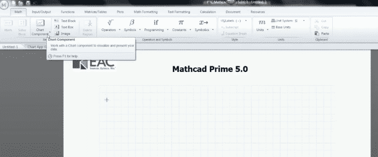
This image shows users where they can find the new charting component in Mathcad Prime 5.0.
Previous to the new release, users were unable to fully control a title, a legend, gridlines, a 2nd y axis, or custom formatting when creating a plot graph under the plots tab. These capabilities are now available in Mathcad Prime 5.0!
Using the new ‘Chart Component’ in Mathcad
Insert a chart component under the math tab – this will insert an empty embedded charting object. If you double click on it, then you can activate the charting application.
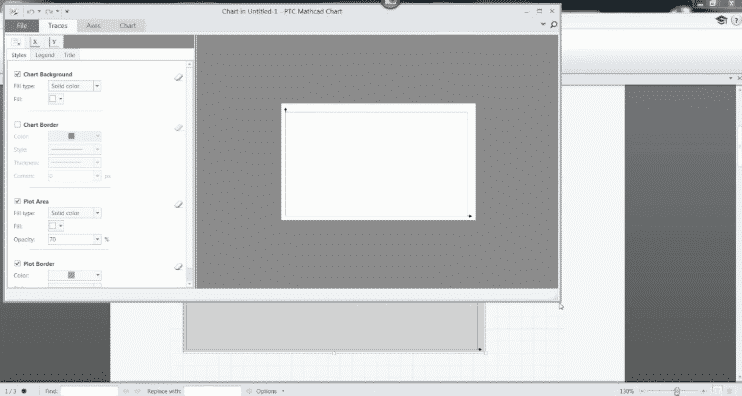 This image shows users the activated charting application once the embedded object is double clicked.
The user can now access all the functionalities of the application that help customize the chart under the plot tab, the x tab, and the y tab such as the title, a border, gridlines, a legend, font, and colors.
Once you close this tab you will see your document again and notice that there is an area above your chart component that says ‘Inputs’. This is where you define the data or function that is needed for the chart to be plotted. You can define either functions or variables that store data. If you click on this section you will see a dropdown of various options in which you can choose to either ‘Insert X-Axis Expression’ or ‘Insert Y-Axis Expression’.
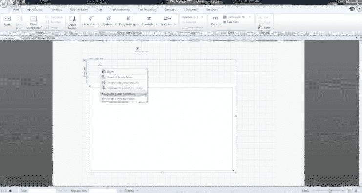 This image shows the user where they can access the insertion of an x and y axis expression in their chart.
Once you’ve entered your x and y axis data, you can double click on the plot again to access a preview of your plot and customize the chart details.
To see what else you can do with Mathcad Prime 5.0, watch PTC’s Anji Seberino demonstrate the advanced chart options available to users by clicking on the video below.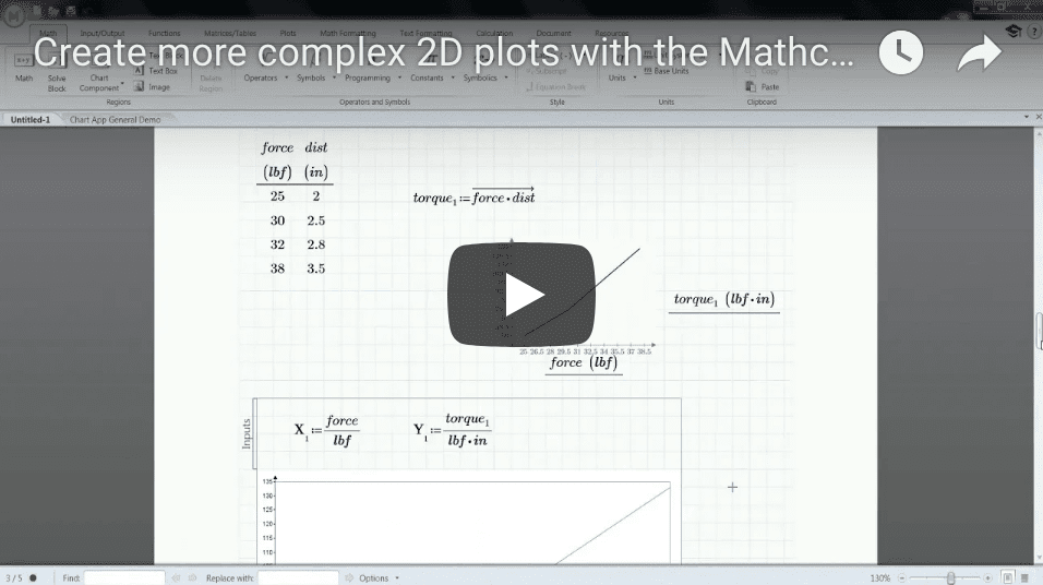
Engineering simulation is the key that will unlock your future innovation. It is the quickest way to validate and optimize designs. These software tools are no longer obscure systems that require specialized skill sets.
Some engineers and designers still shy away from simulation software, but that is quickly changing for two reasons.
1) There have been many improvements to CAD embedded tools like Solidworks Simulation and PTC Creo Simulate.
2) Companies like ANSYS have created easy-to-use upfront simulation tools like AIM and Discovery Live.
This article was written for the people hanging on to outdated misconceptions about engineering simulation. It’s time that everyone realized a few things.
The tools have gotten easier to use and processing power has become more accessible. This has begun to make it easier for engineers to run simulations. It doesn’t take a doctorate or a dedicated super-computer-workstation.
Due to the advancements in technology, eventually every engineer in every industry is going to be able to use engineering simulation. In fact, it could get to the point very soon if you are not using engineering simulation as part of your workflow; you could get left behind. It’s really that much of a competitive advantage when it comes to solving problems quickly.
Engineering simulation no longer needs to be looked at as something scary or complex. It has transformed into something that can be fast, easy to use, and affordable.
Take a look at the ANSYS Discovery product lines for example.
These new engineering simulation tools offer all engineers and designers a fast, simple way to create better products.
The discovery product family is a suite of tools that are designed to put simulation in the hands of every product development engineer. The Discovery family includes; Space Claim, Discovery Live, and Discovery AIM.
Space Claim is a direct modeling tool that provides the ability to quickly edit designs and repair geometry within CAD files. It’s bundled with Discovery Live and AIM to provide an easy way to simply geometry and perform quick design experiments.
Discovery Live is truly an instantaneous simulation tool that is designed for rapid design iterations. You won’t believe until you see it! Real-time concept exploration. No waiting, just results. Make a chance to your design and see simulation results update before your eyes.
Check out our demo on Discovery Live. There’s no “demo magic” here. You’ll see our engineers adjust geometry on-the-fly and quickly run simulations on several changes in a matter of minutes (We often blow people’s minds with this.)
Discovery AIM Complete simulation, driven by an intuitive guided workflow. In-depth concept and design analysis without any coding or guess work. This a high-fidelity tool that provides an entry point into the full power of the ANSYS platform. This multi-physics tool provides a high level of control and the ability to create your own meshes. With AIM’s combined physics workflows your team could easily evaluate how fluids and structures interact. You could look at electric conduction, stress analysis, and even add in additional contacts for assemblies you may want to observe.
The ANSYS Discovery product line really makes simulation accessible. Even an industrial designer that may not have a lot of engineering specific knowledge could use these tools to quickly optimize designs and validate design A versus B (or C, D, E, F, etc. if they feel so inclined).
These basic easy-to-use, affordable tools provide engineers with an entry into using simulation as a part of their workflow.
Don’t believe me yet? Watch this short video to see it for yourself.
Augmented Reality (AR) is a powerful tool used for design reviews, collaboration, and communicating design intent. The AR functionality built into every seat of Creo makes it easier for CAD users to share design info with colleagues, suppliers, customers, and manufacturing partners in a rich, immersive way.
First of all, why use Creo?
PTC Creo, formerly Pro/ENGINEER, is a product design software used by manufacturers for mechanical engineering, design and manufacturing. Creo supports designers from initial concept to design, simulation, and analysis. This CAD tool offers industry-leading capabilities, augmented reality (AR), and the ability to capitalize on the potential of the Internet of Things (IoT) – which enables users to produce better products, more efficiently, and at a lower cost.
Here’s a few examples of how you can benefit from the ability to rapidly create, publish, and share AR experiences directly from Creo.

Creo AR is fundamentally changing the way product stakeholders outside of engineering consume and leverage product data.
Common industry challenges and how to fix them
Share augmented reality experiences
Challenge: You need to quickly, efficiently, and safely get feedback for a design review from a supplier or vendor.
Preparing and packaging models so that people can see them for distribution and review can be a challenge. Engineers typically go through a process of saving a copy the files and keeping track of drawings, assembly, and parts with a risk of compromising intellectual property in the process.
Solution: Creo AR allows you to rapidly define and publish AR experiences that can be distributed instantly only to those who have permission to view it.
Visualize augmented reality experiences
Challenge: You’re unable to convey the size and scale of your design.
It’s difficult to visualize a design if it’s behind a computer screen or you don’t have the means to meet up and physically see the prototype. Engineers can spend a lot of time and money on creating multiple design drafts and prototyping for a short review feedback that could end up relaying to them that more changes need to be made.
Solution: Creo AR allows for immersive design data with full context and scale so that you can interact, explore, and engage with design data.
Creo AR Design Share Extension
The Creo AR Design Share extension allows you to create and manage more augmented reality experiences. The extension allows you to fully control the authoring and accessibility of your company’s AR experiences which protects your intellectual property by preventing access to critical CAD data.
The first 5 AR experiences you create within Creo are free. After that you can purchase the ‘Enterprise package’ which allows you to create 50 models, or the ‘Individual package’ which allows you to create 10 models. Purchasing one of the packages for the Creo AR Design Share extension will also give you permanent shelf life (versus 6 months free) and the administrative control to add and remove authors and viewers as well as add and delete AR experiences.
The value of augmented reality across the Enterprise
Augmented reality goes beyond the ‘cool’ factor. Organizations can make money with the value that AR brings to design, manufacture, selling, service, training, and operations. Talk to our Smart Connected Enterprise experts to learn more about augmented reality.

Designing a product without integrating simulation into your workflow is like giving a concert but never rehearsing. Why would you do that?
Top Performing organizations meet cost targets, remain on spending plans, and beat their due dates. One way they accomplish these objectives is by utilizing simulation tools to empower their organizations. Here’s 10 ways simulation will put you ahead.
1. Simulation software = better design decisions
Simulation tools enable engineers to have better insights throughout the design process.
For example, with the use of simulation engineers can conduct sensitivity studies, analyze trade-offs, remove excess materials and even evaluate motion envelopes.
By using simulation during concept design, engineers are able to explore and consider more options.
These options permit engineers to see the influences and effects of different design guidelines and limitations.
Testing many conditions, simulation software allows engineers to narrow down choices for the best concept.
This is how engineers are able to make better, highly informed design decisions.
2. Simulation helps avoid over engineering
By simulating your designs in a variety of environments, you can easily determine what is necessary within your design and what is not.
This helps engineers eliminate excess materials, and ultimately create better products.
3. With Simulation software, you find problems earlier (while they’re still cheap to fix)
Engineering simulation software helps organizations discover hidden interactions that can cause big problems.
How? It’s simple.
If the materials you’re using to build and design a product can’t perform under stress, you can find out early in the design process.
This helps your design team get it right the first time.
4. Simulation tools improve product quality
Simulation tools enable engineers to analyze and validate the performance of 3D virtual prototypes before the part itself is created.
With the ability to validate and test designs early in the design process, engineers are able to create and evaluate more concepts and ideas within allotted time frames.
This means more ideas, more designs, better quality and ultimately a better product.
5. Simulation software improves product reliability
With simulation software, results are accurate and reliable and can be easily calculated with very little input from engineers.
By using simulation-driven design to optimize product performance, quality and durability- you can be sure that your is more than reliable.
6. Simulation tools cut product development time
Organizations are able to reduce product development time with simulation tools because less time is needed for physical testing, fixing late problems, and rework.
When design engineers know how to run simulations, they understand the requirements for the analysis model. By taking these requirements into consideration as they design, model, and build products, the analysis becomes easier and takes less time to prepare.
7. Innovation is increased with simulation
With the help of simulation tools, engineers can also be more innovative.
Time-savings allotted from simulation and virtual prototypes enable design engineers to evaluate more design iterations.
8. Simulation helps you get to market faster
Simulation tools help streamline product development activities by enabling concurrent design and analysis.
How? It’s simple.
With simulation, the analysis process is faster. For instance, you can forget any reliance on 3rd parties for analysis because you are able to now do it in-house.
By identifying and eliminating errors early in the design process you will resolve errors early, eliminating late-stage changes and tedious rework. This will also greatly speed up your processes.
Simulation tools empower design engineers to make better design decisions.
Better design decisions ultimately produce more competitive products that cost less and get to market faster.
9. In the long run, simulation tools save costs
Simulation helps engineers make better design decisions at much less cost because they can subject virtual models to real-world forces.
By using fewer prototypes and focusing simulation on areas of high sensitivity and fatigue, an organization can save time and money.
For example, engineers can reduce product costs by optimizing designs to meet multiple objectives, such as maintaining a product’s strength while reducing its weight.
This is exactly how the use of analysis and early optimization to properly size geometry can reduce material costs.
Aside from material costs, how do product failures, warranty, and repair cost impact company profits? Tremendously.
Using simulation tools organizations can avoid costly recalls and reduce after-market service, warranty, and repair costs.
It’s easy to see how simulation tools will save you money simply by eliminating the need for project re-work, prototyping, and over-engineering
10. More competitive products
Simulation software provides engineers with additional insight, which leads to better design decisions and product optimization.
By using simulation, design engineers are able to develop higher quality products that are easily differentiated in the market.